- 您现在的位置:买卖IC网 > Sheet目录3871 > PIC18F84J90T-I/PT (Microchip Technology)IC PIC MCU FLASH 8KX16 80TQFP
LPC2104_2105_2106_7
NXP B.V. 2008. All rights reserved.
Product data sheet
Rev. 07 — 20 June 2008
29 of 41
NXP Semiconductors
LPC2104/2105/2106
Single-chip 32-bit microcontrollers
[1]
Typical ratings are not guaranteed. The values listed are at room temperature (+25
°C), nominal supply voltages.
[2]
Internal rail.
[3]
External rail.
[4]
Including voltage on outputs in 3-state mode.
[5]
VDD(3V3) supply voltages must be present.
[6]
3-state outputs go into 3-state mode when VDD(3V3) is grounded.
[7]
Accounts for 100 mV voltage drop in all supply lines.
[8]
Allowed as long as the current limit does not exceed the maximum current allowed by the device.
[9]
Minimum condition for VI = 4.5 V, maximum condition for VI = 5.5 V.
[10] Applies to P0[31:22].
[11] SPI is enabled and SSP is disabled in the PCONP register (
see LPC2104/2105/2106 user manual).
[12] To VSS.
8.1 Power consumption measurements for LPC2104/2105/2106/01
The power consumption measurements represent typical values for the given conditions.
The peripherals were enabled through the PCONP register, but for these measurements
the peripherals were not congured to run. Power measurements with all peripherals
enabled were performed with the SPI enabled and the SSP disabled. Peripherals were
disabled through the PCONP register. Refer to the
LPC2104/2105/2106 User Manual for a
description of the PCONP register.
Oscillator pins
Vi(XTAL1)
input voltage on pin XTAL1
0
-
1.8
V
Vo(XTAL2)
output voltage on pin
XTAL2
0
-
1.8
V
Table 9.
Static characteristics …continued
Tamb =0 °C to +70 °C for commercial applications, unless otherwise specied.
Symbol
Parameter
Conditions
Min
Typ[1]
Max
Unit
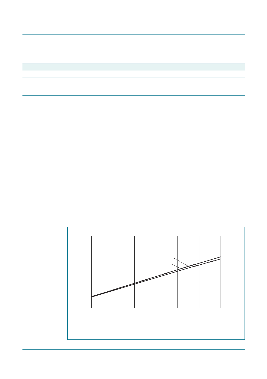
Test conditions: Active mode entered executing code from on-chip ash; PCLK = CCLK
4;
Tamb =25 °C; core voltage 1.8 V.
Fig 5.
Typical LPC2104/2105/2106/01 IDD(act) measured at different frequencies
frequency (MHz)
12
60
44
28
002aad709
20
40
60
IDD(act)
(mA)
0
all peripherals enabled
all peripherals disabled
发布紧急采购,3分钟左右您将得到回复。
相关PDF资料
PIC18F2321T-I/SS
IC PIC MCU FLASH 4KX16 28SSOP
PIC18F2221T-I/SS
IC PIC MCU FLASH 2KX16 28SSOP
PIC18F4682T-I/ML
IC PIC MCU FLASH 40KX16 44QFN
PIC24HJ128GP306T-I/PT
IC PIC MCU FLASH 128KB 64TQFP
PIC24FJ96GA008T-I/PT
IC PIC MCU FLASH 96KB 80TQFP
PIC24FJ64GA010T-I/PT
IC PIC MCU FLASH 64KB 100TQFP
PIC24FJ64GA008T-I/PT
IC PIC MCU FLASH 64KB 80TQFP
PIC18LF4450T-I/PT
IC PIC MCU FLASH 8KX16 44TQFP
相关代理商/技术参数
PIC18F8520-E/PT
功能描述:8位微控制器 -MCU 32KB 2048 RAM 68I/O RoHS:否 制造商:Silicon Labs 核心:8051 处理器系列:C8051F39x 数据总线宽度:8 bit 最大时钟频率:50 MHz 程序存储器大小:16 KB 数据 RAM 大小:1 KB 片上 ADC:Yes 工作电源电压:1.8 V to 3.6 V 工作温度范围:- 40 C to + 105 C 封装 / 箱体:QFN-20 安装风格:SMD/SMT
PIC18F8520-I/PT
功能描述:8位微控制器 -MCU 32KB 2048 RAM 68I/O RoHS:否 制造商:Silicon Labs 核心:8051 处理器系列:C8051F39x 数据总线宽度:8 bit 最大时钟频率:50 MHz 程序存储器大小:16 KB 数据 RAM 大小:1 KB 片上 ADC:Yes 工作电源电压:1.8 V to 3.6 V 工作温度范围:- 40 C to + 105 C 封装 / 箱体:QFN-20 安装风格:SMD/SMT
PIC18F8520-I/PT
制造商:Microchip Technology Inc 功能描述:IC 8BIT FLASH MCU 18F8520 TQFP80
PIC18F8520-I/PTG
功能描述:8位微控制器 -MCU 32KB 2048 RAM 68I/O Lead Free Package RoHS:否 制造商:Silicon Labs 核心:8051 处理器系列:C8051F39x 数据总线宽度:8 bit 最大时钟频率:50 MHz 程序存储器大小:16 KB 数据 RAM 大小:1 KB 片上 ADC:Yes 工作电源电压:1.8 V to 3.6 V 工作温度范围:- 40 C to + 105 C 封装 / 箱体:QFN-20 安装风格:SMD/SMT
PIC18F8520T-E/PT
功能描述:8位微控制器 -MCU 40MHz 32KB Flash RoHS:否 制造商:Silicon Labs 核心:8051 处理器系列:C8051F39x 数据总线宽度:8 bit 最大时钟频率:50 MHz 程序存储器大小:16 KB 数据 RAM 大小:1 KB 片上 ADC:Yes 工作电源电压:1.8 V to 3.6 V 工作温度范围:- 40 C to + 105 C 封装 / 箱体:QFN-20 安装风格:SMD/SMT
PIC18F8520T-I/PT
功能描述:8位微控制器 -MCU 32KB 2048 RAM 68I/O RoHS:否 制造商:Silicon Labs 核心:8051 处理器系列:C8051F39x 数据总线宽度:8 bit 最大时钟频率:50 MHz 程序存储器大小:16 KB 数据 RAM 大小:1 KB 片上 ADC:Yes 工作电源电压:1.8 V to 3.6 V 工作温度范围:- 40 C to + 105 C 封装 / 箱体:QFN-20 安装风格:SMD/SMT
PIC18F8520T-I/PTG
功能描述:8位微控制器 -MCU 32KB 2048 RAM 68I/O Lead Free Package RoHS:否 制造商:Silicon Labs 核心:8051 处理器系列:C8051F39x 数据总线宽度:8 bit 最大时钟频率:50 MHz 程序存储器大小:16 KB 数据 RAM 大小:1 KB 片上 ADC:Yes 工作电源电压:1.8 V to 3.6 V 工作温度范围:- 40 C to + 105 C 封装 / 箱体:QFN-20 安装风格:SMD/SMT
PIC18F8525-E/PT
功能描述:8位微控制器 -MCU 48KB 3840 RAM 68I/O RoHS:否 制造商:Silicon Labs 核心:8051 处理器系列:C8051F39x 数据总线宽度:8 bit 最大时钟频率:50 MHz 程序存储器大小:16 KB 数据 RAM 大小:1 KB 片上 ADC:Yes 工作电源电压:1.8 V to 3.6 V 工作温度范围:- 40 C to + 105 C 封装 / 箱体:QFN-20 安装风格:SMD/SMT